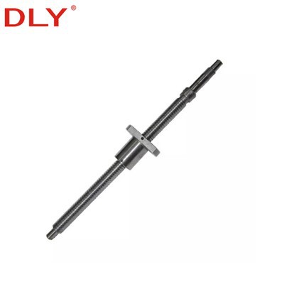
A double ball screw, more accurately called a double nut ball screw, uses two coordinated ball nuts on one screw shaft. Preload between the two nuts reduces axial clearance and increases axial rigidity, helping the transmission maintain stable positioning when the travel direction changes repeatedly.
DLY supplies both DFU and DFI double nut ball screw series. DFU follows a DIN-style flange configuration, while DFI uses a different flange and mounting geometry. The appropriate series should therefore be selected according to the machine mounting space, flange dimensions, screw diameter, lead, load and required stiffness-not by model name alone.
Standard production uses a rolled C7 screw shaft made from S55C and a 20CrMo ball nut. Ground C5 versions, custom shaft length, left-hand thread, end machining and matching support units can be supplied after technical confirmation.
Double nut ball screw assembly
DFU and DFI
Rolled C7
Ground C5
S55C
20CrMo
Right-hand standard; left-hand optional
1 piece

DLY double nut ball screw and screw shaft assembly
Structure and Preload
Each nut contains its own ball circulation path. During operation, the balls roll between the screw raceway and nut raceway, converting rotary motion into controlled linear movement.
The two nuts are assembled with a controlled preload. The preload creates opposing axial forces that reduce clearance between the balls and raceways. Compared with a standard-clearance single nut, this structure provides better axial rigidity and more stable reversal performance.
"Zero backlash" should be understood as a preload objective rather than an unconditional value for every installed system. Actual positioning performance is also affected by screw accuracy, support-bearing clearance, coupling stiffness, mounting alignment, temperature and machine structure.
DFU and DFI Series
| Series | Nut Structure | Mounting Geometry | Diameter Range in Table | Selection Priority |
|---|---|---|---|---|
| DFU | Flanged double nut | DIN-style flange configuration | 16–100 mm | Confirm DFU flange dimensions and nut length |
| DFI | Flanged double nut | DFI-specific flange and mounting dimensions | 16–80 mm | Confirm DFI flange, hole positions and installation space |
DFU and DFI belong to the same double nut ball screw category, but they are not automatically interchangeable. Before replacing an existing unit, compare the nut outside diameter, flange outside diameter, flange thickness, overall nut length, flange width, mounting-hole position and mounting thread.
DFU Dimensions

DFU double nut ball screw structure and dimension symbols
| Model | d | Lead | Da | D | A | B | L | W | X | H | Q | N | Ca | Coa | K |
|---|---|---|---|---|---|---|---|---|---|---|---|---|---|---|---|
| DFU1604-4 | 16 | 4 | 2.381 | 28 | 48 | 10 | 80 | 38 | 5.5 | 40 | M6 | 4 | 629 | 1270 | 42 |
| DFU1605-3 | 16 | 5 | 3.175 | 28 | 48 | 10 | 86 | 38 | 5.5 | 40 | M6 | 3 | 765 | 1240 | 30 |
| DFU1605-4 | 16 | 5 | 3.175 | 28 | 48 | 10 | 100 | 38 | 5.5 | 40 | M6 | 4 | 780 | 1790 | 43 |
| DFU1610-3/2 | 16 | 10 | 3.175 | 28 | 48 | 10 | 96 | 38 | 5.5 | 40 | M6 | 3 | 721 | 1249 | 28 |
| DFU2005-3 | 20 | 5 | 3.175 | 36 | 58 | 10 | 86 | 47 | 6.6 | 44 | M6 | 3 | 860 | 1710 | 42 |
| DFU2005-4 | 20 | 5 | 3.175 | 36 | 58 | 10 | 101 | 47 | 6.6 | 44 | M6 | 4 | 1130 | 2380 | 52 |
| DFU2010-3/2 | 20 | 10 | 3.175 | 36 | 58 | 10 | 96 | 47 | 6.6 | 44 | M6 | 3 | 830 | 1680 | 38 |
| DFU2505-3 | 25 | 5 | 3.175 | 40 | 63 | 10 | 86 | 51 | 6.6 | 48 | M6 | 3 | 980 | 2300 | 60 |
| DFU2505-4 | 25 | 5 | 3.175 | 40 | 63 | 10 | 101 | 51 | 6.6 | 48 | M6 | 4 | 1280 | 3110 | 65 |
| DFU3205-4 | 32 | 5 | 3.175 | 50 | 81 | 12 | 102 | 65 | 9 | 62 | M6 | 4 | 1450 | 4150 | 82 |
| DFU3210-4 | 32 | 10 | 6.350 | 50 | 81 | 14 | 162 | 65 | 9 | 62 | M6 | 4 | 3390 | 7170 | 86 |
| DFU4005-4 | 40 | 5 | 3.175 | 63 | 93 | 14 | 105 | 78 | 9 | 70 | M8 | 4 | 1610 | 5330 | 90 |
| DFU4010-4 | 40 | 10 | 6.350 | 63 | 93 | 14 | 165 | 78 | 9 | 70 | M8 | 4 | 3910 | 9520 | 105 |
| DFU5010-4 | 50 | 10 | 6.350 | 75 | 110 | 16 | 171 | 93 | 11 | 85 | M8 | 4 | 4450 | 12500 | 131 |
| DFU6310-4 | 63 | 10 | 6.350 | 90 | 125 | 18 | 182 | 108 | 11 | 95 | M8 | 4 | 5070 | 16600 | 150 |
| DFU6320-4 | 63 | 20 | 9.525 | 95 | 135 | 20 | 290 | 115 | 13.5 | 100 | M8 | 4 | 7573 | 23860 | 160 |
| DFU8010-4 | 80 | 10 | 6.350 | 105 | 145 | 20 | 182 | 125 | 13.5 | 110 | M8 | 4 | 5620 | 21300 | 182 |
| DFU8020-4 | 80 | 20 | 9.525 | 125 | 165 | 25 | 295 | 145 | 13.5 | 130 | M8 | 4 | 8485 | 30895 | 195 |
| DFU10020-4 | 100 | 20 | 9.525 | 150 | 202 | 30 | 340 | 170 | 17.5 | 155 | M8 | 4 | 9420 | 39183 | 260 |
Dimensions are in mm. Ca and Coa are shown in kgf; K is shown in kgf/μm. Final dimensions and ratings should be confirmed against the approved drawing before ordering.


DFI Dimensions
The DFI series is also a flanged double nut ball screw, but its nut outside diameter, flange size and mounting dimensions differ from the DFU series. The table below should be used together with the approved DFI dimension drawing.

| Model | d | Lead | Da | D | A | B | L | W | H | X | Y | Z | Q | N | Ca | Coa | K |
|---|---|---|---|---|---|---|---|---|---|---|---|---|---|---|---|---|---|
| DFI1604-4* | 16 | 4 | 2.381 | 30/28 | 49 | 10 | 80 | 39 | 34 | 4.5 | 8 | 4.5 | M6 | 4 | 640 | 1340 | 31 |
| DFI1605-3* | 16 | 5 | 3.175 | 30/28 | 49 | 10 | 86 | 39 | 34 | 4.5 | 8 | 4.5 | M6 | 3 | 765 | 1240 | 35 |
| DFI1605-4* | 16 | 5 | 3.175 | 30/28 | 49 | 10 | 100 | 39 | 34 | 4.5 | 8 | 4.5 | M6 | 4 | 780 | 1790 | 45 |
| DFI1610-3/2* | 16 | 10 | 3.175 | 30/28 | 49 | 10 | 96 | 39 | 34 | 4.5 | 8 | 4.5 | M6 | 3 | 833 | 1249 | 30 |
| DFI2005-3* | 20 | 5 | 3.175 | 34/36 | 58 | 10 | 86 | 45 | 40 | 5.5 | 9.5 | 5.5 | M6 | 3 | 860 | 1710 | 43 |
| DFI2005-4 | 20 | 5 | 3.175 | 34/36 | 58 | 10 | 101 | 45 | 40 | 5.5 | 9.5 | 5.5 | M6 | 4 | 1130 | 2380 | 53 |
| DFI2010-3/2* | 20 | 10 | 3.175 | 34/36 | 58 | 10 | 96 | 45 | 40 | 5.5 | 9.5 | 5.5 | M6 | 3 | 760 | 1950 | 48 |
| DFI2505-3 | 25 | 5 | 3.175 | 40 | 63 | 10 | 86 | 51 | 46 | 5.5 | 9.5 | 5.5 | M8 | 3 | 980 | 2300 | 57 |
| DFI2505-4 | 25 | 5 | 3.175 | 40 | 63 | 11 | 101 | 51 | 46 | 5.5 | 9.5 | 5.5 | M8 | 4 | 1280 | 3110 | 63 |
| DFI2510-4/2* | 25 | 10 | 3.175 | 40 | 57 | 10 | 96 | 51 | 44 | 5.5 | 9.5 | 5.5 | M6 | 3 | 830 | 1680 | 53 |
| DFI2510-4* | 25 | 10 | 4.762 | 40 | 72 | 12 | 145 | 51 | 52 | 6.5 | 11 | 6.5 | M6 | 4 | 1944 | 3877 | 65 |
| DFI3205-4 | 32 | 5 | 3.175 | 46/50 | 72 | 12 | 102 | 58 | 52 | 6.5 | 11 | 6.5 | M8 | 4 | 1450 | 4150 | 72 |
| DFI3210-4* | 32 | 10 | 6.350 | 54/50 | 88 | 15 | 162 | 70 | 62 | 9 | 14 | 8.5 | M8 | 4 | 3390 | 7170 | 85 |
| DFI4005-4* | 40 | 5 | 3.175 | 56/50 | 90 | 15 | 105 | 72 | 64 | 9 | 14 | 8.5 | M8 | 4 | 1610 | 5330 | 98 |
| DFI4010-4* | 40 | 10 | 6.350 | 62/63 | 104 | 18 | 165 | 82 | 70 | 11 | 17.5 | 11 | M8 | 4 | 3910 | 9520 | 107 |
| DFI5005-4* | 50 | 5 | 3.175 | 72/75 | 114 | 15 | 105 | 92 | 82 | 11 | 17.5 | 11 | M8 | 4 | 1730 | 6763 | 115 |
| DFI5010-4* | 50 | 10 | 6.350 | 72/75 | 114 | 18 | 171 | 92 | 82 | 11 | 17.5 | 11 | M8 | 4 | 4450 | 12500 | 125 |
| DFI6310-4* | 63 | 10 | 6.350 | 85/90 | 131 | 22 | 182 | 107 | 95 | 14 | 20 | 13 | M8 | 4 | 5070 | 16600 | 140 |
| DFI8010-4 | 80 | 10 | 6.350 | 105 | 148 | 22 | 198 | 125 | 115 | 14 | 20 | 15 | M8 | 4 | 5620 | 21300 | 162 |
| DFI8010-6* | 80 | 10 | 6.350 | 105 | 148 | 22 | 220 | 125 | 110 | 14 | 20 | 15 | M8 | 6 | 7810 | 31800 | 180 |
* Models marked with an asterisk are identified as custom nut specifications in the supplied DFI data. Dimensions are in mm. Ca and Coa are in kgf; K is in kgf/μm. Values such as "30/28" indicate alternative outside-diameter data in the source table and require drawing confirmation.
Model Code

In DFU1605-4 and DFI1605-4, the model code indicates the nut series, nominal screw diameter, lead and circulation configuration:
| Code Section | Meaning | Example |
|---|---|---|
| DFU / DFI | Double nut series and flange configuration | DFU or DFI |
| 16 | Nominal screw diameter | 16 mm |
| 05 | Nominal lead | 5 mm |
| 4 | Number of ball circuits | 4 circuits |
Accuracy and Materials
| Rolled ball screw | C7 is the standard economical option for general automation, packaging machinery and positioning mechanisms. |
|---|---|
| Ground ball screw | C5 is available for applications requiring tighter lead accuracy and more consistent positioning performance. |
| Screw shaft | S55C steel, processed and hardened for ball screw raceway requirements. |
| Ball nut | 20CrMo alloy steel. |
| Preload | Selected according to required axial rigidity, operating torque, load and service life. |
End Machining and Support Units
Shaft ends can be machined according to the customer's drawing or confirmed support-unit dimensions. Available operations include bearing seats, retaining threads, locknut threads, coupling seats, keyways, wrench flats and center holes.
Depending on the screw diameter and machine arrangement, the assembly can be matched with BK/BF, FK/FF or EK/EF support units. End dimensions must be checked together with the fixed-side bearing arrangement, motor coupling and available installation space.
Applications
Feed axes requiring stable reversal and axial rigidity.
Repeated positioning, transfer and assembly mechanisms.
Reciprocating axes with frequent acceleration and deceleration.
Controlled movement where positioning repeatability is important.
Precision motion mechanisms with limited allowable axial play.
Customized ball screw assemblies for integrated linear axes.
Selection Checklist
| Item | Information to Confirm | Why It Matters |
|---|---|---|
| Nut series | DFU or DFI | Determines flange and mounting geometry |
| Diameter and lead | For example, 25 × 5 mm | Affects speed, force and installation size |
| Load | Axial load, peak load and duty cycle | Required for life and load-rating calculation |
| Accuracy | C7 rolled or C5 ground | Must match positioning requirements |
| Speed | Maximum travel speed, stroke and RPM | Used to check critical speed and DN value |
| Shaft length | Overall and threaded-section lengths | Affects buckling and critical speed |
| End machining | Drawing or support-unit model | Ensures correct bearing and motor connection |
| Environment | Dust, coolant, temperature and lubrication | Affects sealing, lubrication and service life |
FAQ
Q: Is a double ball screw the same as a DFU ball screw?
A: No. Double ball screw describes the double-nut structure. DFU is one series within this product category; DFI is another available double-nut series.
Q: Can DFU and DFI ball nuts be interchanged directly?
A: Not necessarily. Their flange dimensions, nut outside diameter, mounting-hole positions and overall length can differ. Installation dimensions must be checked before replacement.
Q: Does every double nut ball screw have absolutely zero backlash?
A: The double-nut preload is designed to minimize axial clearance. Actual system backlash also depends on preload condition, bearing supports, coupling, mounting accuracy, wear and temperature.
Q: Should I choose C7 or C5?
A: C7 rolled ball screws are suitable for general automation and economical positioning. C5 ground ball screws are recommended when tighter lead accuracy and more consistent positioning are required.
Q: Can DLY machine the shaft ends?
A: Yes. End machining can be produced according to an approved drawing or confirmed BK/BF, FK/FF or EK/EF support-unit dimensions.
DFU or DFI Selection Support
Send us the required diameter, lead, shaft length, accuracy grade, load, speed and end-machining drawing. Our team can help confirm the double nut ball screw model and matching support units.
Email: export@dlybearing.com
Contact UsHot Tags: double ball screw, China double ball screw manufacturers, suppliers, factory, ball screw and lead screw, stepper ball screw, 3000mm ball screw, ball screws and actuators co, ballscrews, linear rail ball screw