DFI Internal-Circulation Ball Screw
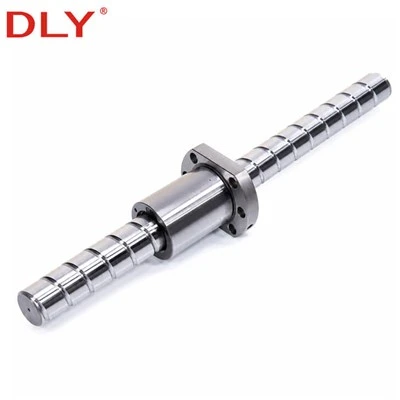
The DLY DFI series is a flange-mounted ball screw assembly with an internal ball-return path and an extended nut body. It is designed for machine axes where the nut is fixed directly to a moving table, carriage or mounting bracket through its flange.
DFI models are available with screw diameters from 16 to 80 mm and leads of 4, 5 or 10 mm. Rolled C7 and ground C5 versions can be supplied according to the positioning requirement. Screw length, shaft-end machining and matching support units are confirmed from the customer's drawing before production.

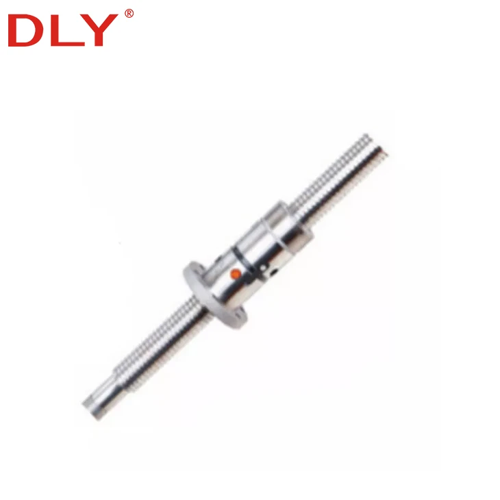
DFI ball screw assembly with internal ball return and flange mounting
DFI Nut Configuration
The DFI nut contains its ball-return path inside the nut body. Because there is no external return tube positioned around the outside of the nut, the return components do not require additional radial installation space. This makes the DFI configuration suitable for assemblies where nearby covers, brackets or machine structures restrict the space around the nut.
The flange forms the mounting interface between the nut and the moving machine component. Its outside diameter, flange width, bolt-hole positions and overall body length are specific to the DFI series. These dimensions must be checked against the machine drawing rather than selecting the product only by screw diameter and lead.
The extended nut arrangement allows axial clearance and preload to be established during assembly. The required setting should be determined from the operating load, direction-change frequency, drive torque and positioning requirement. Final clearance or preload requirements should be confirmed before production.
Product Specifications
| Product Series | DFI |
|---|---|
| Nut Configuration | Flange-mounted extended nut assembly |
| Ball Return Method | Internal circulation |
| Screw Shaft Material | S55C |
| Ball Nut Material | 20CrMo |
| Raceway Surface Hardness | HRC 58–62 |
| Standard Accuracy | Rolled C7 |
| Optional Accuracy | Ground C5; other accuracy requirements subject to confirmation |
| Nominal Diameter Range | 16–80 mm |
| Available Leads | 4, 5 and 10 mm, depending on model |
| Thread Direction | Right-hand standard; left-hand availability subject to confirmation |
| Maximum Available Length | Up to 6,000 mm, depending on diameter, accuracy and production review |
| Shaft-End Machining | Available according to an approved customer drawing |
| Matching Support Units | BK/BF, FK/FF and EK/EF series |
| Minimum Order Quantity | 1 piece |
Specifications are selected by model. The screw diameter, lead, accuracy grade, overall length and shaft-end details must be confirmed together.
How the DFI Assembly Works in a Machine Axis
During operation, the screw shaft rotates while the DFI nut is connected to the moving table or carriage. The balls travel through the loaded raceway and return through passages contained within the nut. Rotation of the shaft is therefore converted into controlled linear movement of the mounted component.
On an axis that changes direction repeatedly, the nut setting affects axial movement at the reversal point. The DFI assembly can be prepared according to the specified clearance or preload requirement, but this setting must also be considered together with motor torque, support-bearing arrangement, screw length and required positioning performance.
A complete DFI order can include the threaded shaft, fitted nut, customer-specified end machining and corresponding fixed-side and supported-side bearing units. Confirming these components on one drawing allows the shaft shoulders, bearing seats, locknut threads and coupling connection to be checked before machine assembly.
Information Required for Model Selection
A DFI model number identifies the nominal shaft diameter, lead and circulation specification, but it does not define the complete machined assembly. The following information is normally required before quotation and drawing confirmation.
Motion requirement
Required stroke, total shaft length, lead, travel speed and operating orientation.
Load condition
Axial load, acceleration, duty cycle and frequency of direction changes.
Accuracy requirement
Requested accuracy grade, axial-clearance requirement and positioning target.
Installation details
Nut mounting space, bearing arrangement, motor connection and shaft-end drawing.
When replacing an existing assembly, send the complete model number and a drawing or clear dimensional photographs. Products with the same nominal diameter and lead may still have different flange dimensions, body lengths or mounting-hole positions.
Available DFI Models
| Nominal Diameter | 4 mm Lead | 5 mm Lead | 10 mm Lead |
|---|---|---|---|
| 16 mm | DFI1604 | DFI1605 | DFI1610 |
| 20 mm | - | DFI2005 | DFI2010 |
| 25 mm | - | DFI2505 | DFI2510 |
| 32 mm | - | DFI3205 | DFI3210 |
| 40 mm | - | DFI4005 | DFI4010 |
| 50 mm | - | DFI5005 | DFI5010 |
| 63 mm | - | - | DFI6310 |
| 80 mm | - | - | DFI8010 |
DFI Dimensions and Load Data
The table provides the nut mounting dimensions and reference load data for the listed DFI specifications. Select the model first, then verify the nut diameter, flange dimensions, mounting holes and overall nut length against the machine design.
| Custom | Model | d | Lead | Da | D | A | B | L | W | H | X | Y | Z | Q | N | Ca | Coa | K |
|---|---|---|---|---|---|---|---|---|---|---|---|---|---|---|---|---|---|---|
| ★ | DFI1604-4 | 16 | 4 | 2.381 | 30/28 | 49 | 10 | 80 | 39 | 34 | 4.5 | 8 | 4.5 | M6 | 4 | 640 | 1340 | 31 |
| ★ | DFI1605-3 | 16 | 5 | 3.175 | 30/28 | 49 | 10 | 86 | 39 | 34 | 4.5 | 8 | 4.5 | M6 | 3 | 765 | 1240 | 35 |
| ★ | DFI1605-4 | 16 | 5 | 3.175 | 30/28 | 49 | 10 | 100 | 39 | 34 | 4.5 | 8 | 4.5 | M6 | 4 | 780 | 1790 | 45 |
| ★ | DFI1610-3/2 | 16 | 10 | 3.175 | 30/28 | 49 | 10 | 96 | 39 | 34 | 4.5 | 8 | 4.5 | M6 | 3 | 833 | 1249 | 30 |
| ★ | DFI2005-3 | 20 | 5 | 3.175 | 34/36 | 58 | 10 | 86 | 45 | 40 | 5.5 | 9.5 | 5.5 | M6 | 3 | 860 | 1710 | 43 |
| ★ | DFI4010-4 | 40 | 10 | 6.350 | 62/63 | 104 | 18 | 165 | 82 | 70 | 11 | 17.5 | 11 | M8 | 4 | 3910 | 9520 | 107 |
| ★ | DFI5005-4 | 50 | 5 | 3.175 | 72/75 | 114 | 15 | 105 | 92 | 82 | 11 | 17.5 | 11 | M8 | 4 | 1730 | 6763 | 115 |
| ★ | DFI5010-4 | 50 | 10 | 6.350 | 72/75 | 114 | 18 | 171 | 92 | 82 | 11 | 17.5 | 11 | M8 | 4 | 4450 | 12500 | 125 |
| ★ | DFI6310-4 | 63 | 10 | 6.350 | 85/90 | 131 | 22 | 182 | 107 | 95 | 14 | 20 | 13 | M8 | 4 | 5070 | 16600 | 140 |
| DFI8010-4 | 80 | 10 | 6.350 | 105 | 148 | 22 | 198 | 125 | 115 | 14 | 20 | 15 | M8 | 4 | 5620 | 21300 | 162 | |
| ★ | DFI8010-6 | 80 | 10 | 6.350 | 105 | 148 | 22 | 220 | 125 | 110 | 14 | 20 | 15 | M8 | 6 | 7810 | 31800 | 180 |
★ indicates a custom-made nut specification. Dimensions are in millimetres. Ca and Coa are reference load values in kgf, and K is the reference rigidity value in kgf/μm. Final dimensions and performance requirements must be confirmed before production.
Available Supply Configuration
DFI products can be supplied as a screw-and-nut assembly or prepared as part of a machine-axis component package. When end machining is required, DLY produces the bearing seats, shoulders, threads and coupling connection according to the approved drawing.
| Supply Item | Information to Confirm |
|---|---|
| DFI screw and nut | Model, accuracy grade, screw length and axial-clearance requirement |
| Machined screw assembly | Complete shaft-end drawing with dimensions, tolerances and thread details |
| Assembly with support units | Fixed-side and supported-side bearing-unit series and mounting arrangement |
| Replacement assembly | Existing model number, drawing, key measurements and application information |
Typical DFI Installation Requirements
DFI assemblies can be considered for CNC feed axes, industrial positioning tables, machining equipment and automated mechanisms that use a flange-mounted nut. The deciding factor is whether the DFI mounting envelope, travel requirement and load data correspond to the machine design.
For long strokes or higher operating speeds, the screw's critical speed, support distance and installation alignment should be checked before the final diameter is selected. For vertical installation, the moving mass and holding arrangement must also be included in the selection information.
Correct alignment between the screw shaft, support bearings and nut mounting surface is necessary during installation. The nut should not be forced into position to compensate for an offset mounting bracket, as this can introduce additional resistance and uneven raceway loading.
Request a DFI Ball Screw Quotation
Send the required DFI model, screw length, quantity, accuracy grade and shaft-end drawing. If the model has not been selected, include the stroke, load, speed and installation information for review.
Hot Tags: dfi ball screw, China dfi ball screw manufacturers, suppliers, factory, ball screw drive, brass ball screw, ball screw coupler, ball screw 20mm, miniature ball screw assembly, 12mm ball screw