


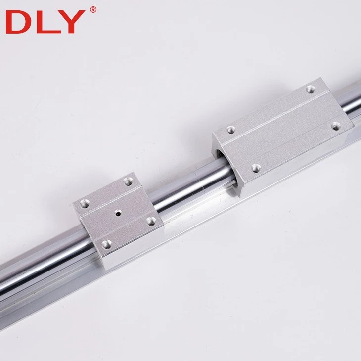
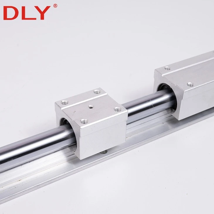
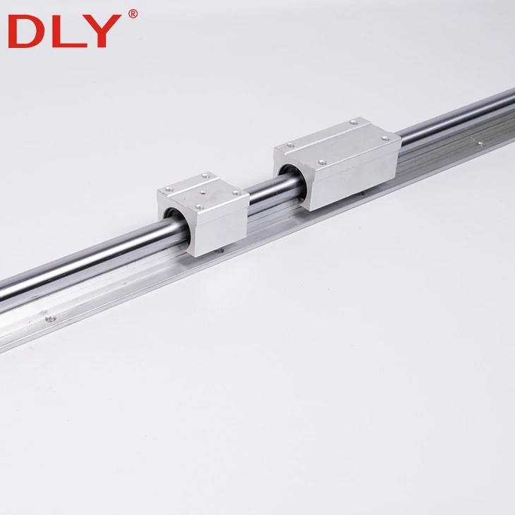
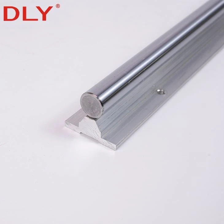
The SBR16 linear shaft is a continuously supported 16 mm round rail for machine axes that require more shaft rigidity and a longer available rail length than smaller supported-shaft systems. The round shaft is fixed along a support profile instead of being suspended only between two end supports, allowing the machine base to support the guide throughout its travel.
With a 17.8 mm shaft center height, 40 mm base width and 150 mm mounting-hole pitch, SBR16 provides a practical layout for compact and medium-size automation equipment. Its maximum single-piece length is 6000 mm, making it suitable for axes that exceed the length range normally associated with smaller supported shafts.
Bearing steel and high-carbon steel shaft materials are available. Additional supported and unsupported shaft configurations can be found in the linear shaft product range.
Why Use a 16 mm Supported Rail?
Selecting a supported round guide is not based on shaft diameter alone. The machine designer must also consider travel length, carriage spacing, mounting width and the stiffness of the machine base. A 16 mm shaft provides a larger cross-section than compact supported rails, while the continuous lower support reduces the unsupported span of the shaft.
This makes SBR16 useful when the installation still needs a relatively compact round-guide system but the required travel or working load makes a smaller shaft unsuitable. The 40 mm support-base width also provides a broader mounting footprint without changing to a profile linear guide structure.
Dimensional Layout
The following dimensions correspond to the SB16 supported round-guide drawing. Lettered dimensions should be checked together with the product drawing when preparing the machine mounting surface.
| Parameter | Symbol | SB16 Specification |
|---|---|---|
| Shaft diameter | d | 16 mm |
| Drawing dimension | E | 20 mm |
| Overall height | h | 25 mm |
| Support-base width | B | 40 mm |
| Shaft center height | H | 17.8 mm |
| Base thickness | T | 5 mm |
| Drawing dimension | F | 18.5 mm |
| Drawing dimension | X | 8 mm |
| Side height | Y | 11.7 mm |
| Support-body width | C | 30 mm |
| Support angle | θ | 60°/80° |
| Drawing hole dimension | S1 | Ø5.5 mm |
| Drawing dimension | a1 | 6 mm |
| Drawing dimension | a2 | 9.5 mm |
| Mounting-hole diameter | d1 | 5.5 mm |
| Rail weight | - | 2.56 kg/m |
Rail Length Planning
SB16 standard lengths are 190, 340, 640 and 940 mm. These lengths are arranged around a 150 mm mounting-hole pitch with a nominal end distance of 20 mm. They are useful when the rail can be incorporated into a standard machine layout without relocating the mounting holes.
Custom lengths can be produced up to 6000 mm. When the required length does not correspond to a standard pattern, the final end distances and mounting-hole positions must be established before machining. Lengths above 6000 mm can be divided into joined sections according to the machine drawing.
Material Options
The SBR16 shaft is available in bearing steel or high-carbon steel. Material selection should be made together with the required surface condition, operating environment and mating linear-bearing arrangement.
Material terms should not be treated as a complete performance specification. If a project has defined requirements for surface hardness, hardened-layer depth, diameter tolerance, straightness or surface finish, those values should be stated separately on the technical drawing.
Machine Design Notes
| Design Item | SBR16 Consideration |
|---|---|
| Mounting base | Provide continuous support beneath the rail and avoid forcing the rail to follow an uneven machine surface. |
| Parallel rail arrangement | Use one rail as the alignment reference, then adjust the second rail according to the carriage movement. |
| Bearing block | Use an open-type linear bearing block designed for a 16 mm supported shaft and confirm whether blocks are included in the supply. |
| Joined rails | Locate joints away from critical load transitions where possible and verify carriage passage across each joint. |
| Load assessment | Consider load direction, block spacing, rail spacing, speed and duty cycle instead of selecting by shaft diameter alone. |
Suitable Equipment
SBR16 supported linear shafts are used in inspection machines, compact processing equipment, packaging mechanisms, material-transfer devices and general automation axes. The 16 mm size is especially relevant when the machine requires a longer supported travel than a compact shaft system can conveniently provide, but does not require the installation profile of a larger supported rail.
For a more compact 12 mm installation, refer to the SBR12 linear shaft. Where a wider base and larger shaft diameter are required, see the SBR25 linear shaft.
Custom Supply
DLY supplies SBR16 rails from one piece, with standard lengths, custom-cut lengths and drawing-based hole layouts available. A complete request should identify the required rail length, quantity, material, mounting-hole arrangement and whether matching bearing blocks are needed.
For SBR16 dimensional confirmation or a custom rail layout, send the required length and machine drawing for technical review.
Contact UsHot Tags: sbr16 linear shaft, China sbr16 linear shaft manufacturers, suppliers, factory, cam roller linear guide rails, profile rail linear guides, 30mm linear shaft, Sbr Linear Guide Rail, High Carbon Steel Optical Shaft, round shaft linear bearings


