


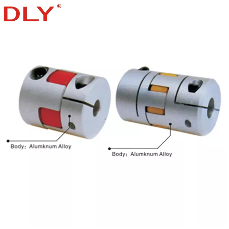
The DLK8 clamp type curved jaw coupling uses two aluminum alloy hubs and a polyurethane elastomer to transmit torque between two shafts. The elastomer absorbs vibration and accommodates parallel, angular and axial misalignment, helping reduce the transmission of shock loads between connected components.
Unlike a point-contact set screw connection, the split clamp hubs apply clamping force around the shaft circumference. This provides secure shaft retention and makes installation or removal possible without causing direct set-screw marks on the shaft surface.
The DLK8 series includes 11 standard body sizes with outside diameters from 14 to 105 mm, rated torque from 1.1 to 430 N·m, and maximum rotational speeds up to 19,000 rpm. Different d1 and d2 bore combinations can be selected to connect shafts of identical or different diameters.
Product: Clamp Type Curved Jaw Coupling
Series: DLK8
Hub Material: Aluminum Alloy
Elastomer Material: Polyurethane
Outside Diameter: 14–105 mm
Rated Torque: 1.1–430 N·m
Maximum Torque: 2.2–860 N·m
DLK8 Clamp Type Curved Jaw Coupling
A curved jaw coupling consists of two metal hubs and an elastic insert positioned between the interlocking jaws. Torque is transferred from one hub to the other through the polyurethane elastomer. The flexible insert cushions vibration and allows limited relative displacement between the two connected shafts.
The clamp-style hubs are tightened by socket screws. Clamping force is distributed around the bore instead of being concentrated at one point, providing reliable shaft engagement and good concentricity for motors, ball screw assemblies, linear modules and other motion-control equipment.
Clockwise and counterclockwise rotational characteristics are the same. Two elastomer hardness options are available to balance torsional stiffness and vibration absorption according to the operating requirements.
Product Features
- Aluminum alloy hubs provide a lightweight structure with low rotational inertia.
- Polyurethane elastomer absorbs vibration and cushions shock loads.
- Compensates for limited parallel, angular and axial shaft misalignment.
- Split clamp hubs provide secure shaft retention without direct set-screw contact on the shaft surface.
- Identical clockwise and counterclockwise rotational characteristics.
- Elastomer offers oil resistance and electrical insulation.
- Two elastomer hardness options are available.
- Standard bore combinations and customized d1/d2 bores are available.
Model Number Identification
| Code | Meaning | Example |
|---|---|---|
| DLK8 | Product series | DLK8 |
| C40 | 40 mm outside diameter, clamp type | C40 |
| 14 | d1 bore diameter: 14 mm | 14 |
| 18 | d2 bore diameter: 18 mm | 18 |
Complete model example: DLK8-C40-1418
This model has a 40 mm outside diameter, a 14 mm d1 bore and an 18 mm d2 bore.
If a keyway is required, add K after the outside-diameter code. For example, DLK8-C40K-1418 represents a C40 coupling with 14 mm and 18 mm bores and a customized keyway.
Standard Bore Options and Dimensions
The two coupling hubs may use the same bore diameter or different d1 and d2 diameters. The available standard bore options for each body size are listed below. Bore combinations outside these ranges should be confirmed with DLY before ordering.
| Model | Standard d1/d2 Bores (mm) | D (mm) | L (mm) | L1 (mm) | L2 (mm) | S (mm) | L3 (mm) | M | Wrench Torque (N·m) |
|---|---|---|---|---|---|---|---|---|---|
| DLK8-C14 | 2 / 3 / 4 / 5 / 6 / 7 | 14 | 22 | 7 | 6 | 1 | 3.5 | M2.5 | 1 |
| DLK8-C20 | 4 / 5 / 6 / 6.35 | 20 | 30 | 10 | 8 | 1 | 5 | M3 | 1.3 |
| DLK8-C25 | 4 / 5 / 6 / 6.35 / 8 / 10 / 11 / 12 | 25 | 34 | 11 | 10 | 1 | 5 | M4 | 1.5 |
| DLK8-C30 | 8 / 9.525 / 10 / 12 / 14 / 16 | 30 | 35 | 11 | 10 | 1.5 | 5 | M4 | 1.7 |
| DLK8-C40S | 14 / 16 / 19 / 20 / 22 / 24 | 40 | 55 | 19.5 | 12 | 2 | 10 | M6 | 8 |
| DLK8-C40 | 14 / 16 / 18 / 19 / 20 / 22 / 24 | 40 | 66 | 25 | 12 | 2 | 10 | M6 | 8 |
| DLK8-C55 | 14 / 16 / 19 / 24 / 25 / 28 | 55 | 78 | 30 | 14 | 2 | 10 | M6 | 8 |
| DLK8-C65 | 19 / 20 / 24 / 28 / 30 / 35 / 38 | 65 | 90 | 35 | 15 | 2.5 | 15 | M8 | 15 |
| DLK8-C80 | 24 / 28 / 30 / 35 / 38 / 40 / 45 | 80 | 114 | 45 | 18 | 3 | 15 | M8 | 15 |
| DLK8-C95 | 30 / 35 / 38 / 40 / 50 / 55 | 95 | 126 | 50 | 20 | 3 | 20 | M10 | 25 |
| DLK8-C105 | 35 / 40 / 45 / 50 / 55 / 60 | 105 | 140 | 56 | 21 | 3.5 | 21 | M12 | 35 |
Technical Specifications
| Model | Rated Torque (N·m) |
Maximum Torque (N·m) |
Maximum Speed (rpm) |
Moment of Inertia (kg·m²) |
Torsional Stiffness (N·m/rad) |
Parallel Misalignment (mm) |
Angular Misalignment (°) |
Axial Misalignment (mm) |
Mass (g) |
|---|---|---|---|---|---|---|---|---|---|
| DLK8-C14 | 1.1 | 2.2 | 19,000 | 5.9 × 10⁻⁴ | 46 | 0.02 | 1.0 | 0 to +0.60 | 26 |
| DLK8-C20 | 2.8 | 5.6 | 17,000 | 6.7 × 10⁻⁴ | 55 | 0.02 | 1.0 | 0 to +0.60 | 37 |
| DLK8-C25 | 6 | 12 | 16,000 | 7.6 × 10⁻⁴ | 63 | 0.02 | 1.0 | 0 to +0.60 | 42 |
| DLK8-C30 | 6.5 | 13 | 12,000 | 8.5 × 10⁻⁴ | 72 | 0.02 | 1.0 | 0 to +0.60 | 50 |
| DLK8-C40S | 32 | 64 | 10,000 | 9.4 × 10⁻⁴ | 500 | 0.02 | 1.0 | 0 to +0.80 | 150 |
| DLK8-C40 | 32 | 64 | 10,000 | 1.1 × 10⁻³ | 550 | 0.02 | 1.0 | 0 to +0.80 | 156 |
| DLK8-C55 | 46 | 92 | 8,000 | 4.4 × 10⁻³ | 1,500 | 0.02 | 1.0 | 0 to +0.80 | 362 |
| DLK8-C65 | 109 | 218 | 6,000 | 9 × 10⁻³ | 2,800 | 0.02 | 1.0 | 0 to +0.80 | 582 |
| DLK8-C80 | 135 | 270 | 4,600 | 1.8 × 10⁻³ | 3,500 | 0.02 | 1.0 | 0 to +1.00 | 966 |
| DLK8-C95 | 260 | 520 | 3,800 | 2 × 10⁻² | 4,600 | 0.02 | 1.0 | 0 to +1.00 | 1,820 |
| DLK8-C105 | 430 | 860 | 3,400 | 3.2 × 10⁻² | 5,800 | 0.02 | 1.0 | 0 to +1.00 | 2,430 |
Note: Moment of inertia and mass values are calculated using the maximum available shaft bore for each coupling size.
DLK8 Coupling Selection
Selection should be based on transmitted torque, shaft diameters, rotational speed and expected shaft misalignment. The following points should be confirmed before placing an order:
- Confirm both shaft diameters: Specify the motor-side d1 bore and driven-side d2 bore. The two bores do not need to be identical.
- Check operating torque: Normal operating torque should remain within the rated torque of the selected model. Starting, braking and shock loads must also be considered.
- Check rotational speed: The operating speed must not exceed the maximum speed listed for the coupling size.
- Check shaft alignment: Actual parallel, angular and axial misalignment must remain within the specified limits.
- Confirm special machining: State whether a keyway, non-standard bore or other machining is required.
Ordering information: Please provide the required torque, rotational speed, d1 shaft diameter, d2 shaft diameter and whether a keyway is required. DLY can then confirm the appropriate model and bore combination.
Typical Applications
- Servo motor and stepper motor connections
- Ball screw drive assemblies
- Linear modules and positioning stages
- CNC and automated production equipment
- Packaging and printing machinery
- Inspection and measuring equipment
- Pumps, encoders and general transmission systems
Frequently Asked Questions
Can the d1 and d2 bore diameters be different?Request a DLK8 Coupling Quotation
Send the required model, d1 and d2 shaft diameters, operating torque, speed and keyway requirements for selection confirmation.
Email: export@dlybearing.com
Hot Tags: clamp type curved jaw coupling, China clamp type curved jaw coupling manufacturers, suppliers, factory


