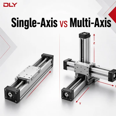
A single-axis linear stage moves a load in one controlled direction, while a multi-axis linear motion system combines two or more axes to position the load in a plane or three-dimensional space. The difference is not simply the number of linear modules. Multi-axis equipment also requires coordinated control, sufficient structural rigidity, cable management and careful consideration of accumulated positioning errors.
For buyers, the practical question is whether the application needs only one independent movement or coordinated positioning in X, Y and Z directions. This guide compares the main system structures and explains what information should be confirmed before selection.
The Basic Difference
A single-axis linear stage produces controlled movement along one straight path. Depending on its installation direction, that path may be described as the X, Y or Z axis. A single-axis stage may be used for feeding, pushing, lifting, positioning, dispensing or transferring a workpiece.
A multi-axis linear motion system is an assembly of two or more motion axes. The axes are mounted together so that the end tool, fixture or workpiece can reach different positions in a two-dimensional or three-dimensional working area.
In other words, a multi-axis system is normally not a completely different type of linear module. It is a motion structure created by combining suitably selected axes with mounting plates, motors, sensors, cables and a motion controller.
Single-Axis vs Multi-Axis Linear Motion System
| Comparison | Single-Axis Stage | Multi-Axis System |
|---|---|---|
| Movement | One linear direction | Two or more coordinated directions |
| Typical structures | X, Y or Z axis | XY, XZ, XYZ or gantry |
| Mechanical design | Relatively simple installation and alignment | Requires axis mounting, rigidity and orthogonality checks |
| Control | One motor and one motion channel | Multiple motors and coordinated motion control |
| Load calculation | Payload and external forces act on one stage | Lower axes may carry the payload plus upper axes, motors and tooling |
| Accuracy | Affected mainly by the selected axis and its installation | Also affected by mounting error, perpendicularity and structural deflection |
| System cost | Lower component and integration cost | Higher mechanical, electrical and commissioning cost |
| Typical applications | Feeding, pressing, lifting and linear transfer | Dispensing, inspection, pick-and-place and CNC positioning |
Common Multi-Axis Configurations
XY Linear Motion System
An XY system moves a load across a horizontal plane. One axis is mounted on and carried by the other, so the lower axis must support the moving mass of the upper axis, motor, mounting plate, workpiece and tooling. Typical applications include inspection, marking, dispensing and component positioning.
XZ Linear Motion System
An XZ system combines horizontal travel with vertical lifting. The vertical axis requires particular attention because gravity continuously acts on the load. Motor holding torque, braking, ball screw back-driving risk and protection against an uncontrolled drop must all be considered.
XYZ Linear Motion System
An XYZ system can position a tool or workpiece in three dimensions. It is suitable for automated assembly, measurement, dispensing and pick-and-place tasks. The base axis normally carries the greatest total moving mass, while the upper axes must remain sufficiently compact to reduce inertia and structural deflection.
Gantry System
A gantry system supports a cross-axis from two sides and is often selected for a wider working area or a load that creates a large overturning moment. If two parallel drive axes are used, they must remain synchronized to prevent racking, binding or uneven guide loading.
Factors That Affect Linear Motion System Selection
1. Required Motion Path
Start with the actual process rather than the desired number of axes. A component that only moves between two positions may require one axis. A dispensing head that must cover a flat working area normally requires XY motion, while a process that also needs lifting or depth adjustment may require XYZ motion.
2. Effective Stroke and Installation Space
Effective stroke is the usable travel required by the application. It is not the same as the overall length of the module. Space must also be reserved for the motor, coupling or gearbox, sensors, cable routing and maintenance access.
3. Load, Force and Moment
Do not select a module by payload weight alone. The calculation should include tooling, fixtures, upper axes, motors, acceleration forces and process forces. An offset load creates pitch, roll or yaw moments that may overload the guide blocks even when the total payload appears acceptable.
4. Speed, Acceleration and Cycle Time
High acceleration increases motor torque demand and the dynamic load applied to the module. A lighter upper-axis structure may be necessary for a fast multi-axis system. When the application has a long stroke or high travel speed, the ball screw critical speed, screw support arrangement and drive type must also be checked.
5. Positioning Accuracy and Repeatability
Positioning accuracy describes how closely the stage reaches the commanded coordinate. Repeatability describes how consistently it returns to the same position. A multi-axis system must additionally control perpendicularity between axes, mounting surface accuracy, structural deflection and calibration error.
Therefore, selecting several accurate single-axis modules does not automatically guarantee the same accuracy at the tool center point after assembly.
6. Operating Environment
Dust, metal chips, oil mist, humidity and other contaminants affect the required protection structure. Open modules allow easier access, while semi-enclosed or enclosed modules provide better protection for the ball screw and guide components. Cable chains and sensor protection should be planned at the system design stage.
7. Motor and Control Method
A single-axis application may use a relatively simple stepper or servo control arrangement. Coordinated multi-axis interpolation normally requires a compatible motion controller, suitable drives and correctly configured feedback. Motor type, flange dimensions, brake requirement and encoder arrangement should be confirmed before the mechanical interface is finalized.
Which Structure Is Suitable for Your Application?
| Application Requirement | Possible Structure | Main Selection Concern |
|---|---|---|
| Move a part between two fixed positions | Single axis | Stroke, speed, load and positioning requirement |
| Dispense or inspect across a flat area | XY system | Working area, upper-axis mass and axis perpendicularity |
| Move horizontally and lift a load | XZ system | Vertical load, holding brake and drop prevention |
| Position a tool throughout a 3D workspace | XYZ system | Accumulated load, rigidity, control and system calibration |
| Cover a wide span or carry a large offset load | Gantry system | Cross-beam rigidity and synchronized parallel axes |
Information Required for Linear Module Selection
To select a single-axis or multi-axis linear module, provide the following information for each axis:
- Required axis arrangement: single axis, XY, XZ, XYZ or gantry
- Effective stroke of each axis
- Horizontal, vertical or inclined installation
- Total moving mass, including tooling and upper axes
- Location of the load center and any overhung load
- Required speed, acceleration and cycle time
- Positioning accuracy and repeatability requirement
- Motor type, power and flange dimensions
- Operating environment and required enclosure
- Available installation space
Providing only the stroke and payload is often insufficient for a multi-axis system. A layout drawing showing the axis orientation, mounting direction and load position helps DLY evaluate the structure more accurately.
FAQ
Can single-axis linear modules be combined into an XY or XYZ system?
Yes. However, the modules should not be selected independently. The lower axis must be sized for the combined moving mass, and the mounting interface, rigidity, motor orientation, sensors and cable routing must be planned for the complete assembly.
Does a multi-axis system always need servo motors?
No. Stepper motors may be suitable for some moderate-speed positioning tasks. Servo motors are generally preferred when the application requires higher speed, closed-loop feedback, faster acceleration or more demanding coordinated motion. The decision should be based on the complete motion profile.
Which axis should be selected first in an XYZ system?
The selection process should start with the moving tool and the uppermost axis, then work downward. Each lower axis must be recalculated after adding the mass of all components installed above it.
Is the accuracy of an XYZ system equal to the accuracy of each module?
Not necessarily. The final tool-point accuracy is also influenced by axis alignment, perpendicularity, mounting surface accuracy, structural deflection, feedback arrangement and calibration.
DLY supplies ball screw linear modules and linear motion stages for single-axis and combined multi-axis applications. Send us your axis arrangement, stroke, load, speed, accuracy, motor and installation requirements for model selection.
Email: dlyexport2@dlybearing.com | WhatsApp: +86 166 0578 8856