


Accurate linear guideway alignment depends on more than placing two rails at an equal distance. The mounting surface, reference shoulder, master rail, secondary rail and carriage mounting plate must work together as one geometric system.
A guideway may feel smooth during a short manual test and still be misaligned. As the carriage travels farther, lateral loading, uneven running resistance, noise or premature raceway wear may appear. The correct method is to establish one rail as the reference, align the second rail to it and verify both lateral parallelism and height variation over the complete stroke.
What Tools Are Needed?
| Tool | Purpose |
|---|---|
| Dial indicator with rigid stand | Measures lateral and vertical deviation along the stroke |
| Precision straightedge or alignment reference | Provides an independent datum for the master rail |
| Precision level | Checks machine-base level and large-scale inclination |
| Torque wrench | Applies consistent final bolt torque |
| Soft-faced mallet and rail clamps | Makes small position corrections without striking the hardened rail directly |
| Lint-free cloth and cleaning agent | Removes oil, burrs and contamination from the mounting surfaces |
For high-precision or long-travel equipment, an electronic level, granite reference or laser measurement system may also be required. The measurement method should match the machine's specified tolerance rather than relying on a universal alignment value.
Step 1: Inspect the Mounting Base
Clean the rail mounting surface, reference shoulder and bolt holes thoroughly. Remove paint, raised edges, metal chips and burrs. A small particle trapped below the rail can create local height error and may cause the rail to bend when the mounting bolts are tightened.
Before installing the rail, verify:
- The mounting surface is flat and free from local damage.
- The reference shoulder is straight and perpendicular to the mounting surface.
- The mounting holes do not contain chips or raised material.
- The base is sufficiently rigid to support the selected guideway.
- The rail and blocks have no transportation damage or raceway contamination.
Shims should not be used randomly to compensate for a poorly machined base. If height correction is part of the machine design, use controlled, stable shimming at defined positions and remeasure the complete surface.
Step 2: Install and Align the Master Rail
In a dual-rail system, select one rail as the master rail. This rail establishes the travel direction for the entire axis. Position it against the machined reference shoulder, but initially tighten the mounting bolts only enough to keep the rail in place.
If a reliable shoulder is available, use clamps or lateral set plates to seat the rail evenly against it. If there is no machined shoulder, align the rail against an independent precision reference using a dial indicator, straightedge or laser system.
- Position the rail and install all mounting bolts loosely.
- Establish the lateral position at the first measurement section.
- Move along the rail in short sections and make small corrections.
- Lightly tighten each completed section to hold its position.
- Apply the specified final torque gradually, following the machine or guideway installation requirements.
- Measure the rail again after final tightening.
Tightening all bolts at one end before checking the remaining length can push the alignment error toward the opposite end. Alignment and tightening should therefore progress in controlled sections.
Step 3: Align the Secondary Rail
After the master rail is fixed, place the secondary rail in position with its mounting bolts slightly loose. The secondary rail must be aligned relative to the master rail-not independently relative to an unrelated edge of the machine base.
Mount a dial indicator on a stable fixture connected to the master-rail carriage or measurement bridge. Place the indicator probe against the reference side of the secondary rail or a suitable carriage reference. Move the fixture over the complete stroke and record the reading at multiple positions.
At each measurement section, gently adjust the secondary rail until the indicator reading is within the tolerance specified by the machine drawing or guideway manufacturer. Lightly secure that section before continuing to the next position.
For a more detailed comparison of measurement methods, see how to measure linear guide parallelism .
Step 4: Check Height and Coplanarity
Lateral parallelism alone is not enough. The block mounting surfaces on both rails must also be at the correct relative height. Excessive height difference can twist the carriage plate and create unequal loading among the blocks.
Use a dial indicator, precision level or measurement bridge to check the upper mounting surfaces of the blocks along the full stroke. If the readings vary significantly, inspect the mounting base before attempting to correct the rail itself.
Do not pull a rail downward with excessive bolt torque or use the carriage plate to flatten an inaccurate base. This may make the assembly appear aligned while storing stress in the rail, blocks and machine table.
Step 5: Install the Moving Table and Tighten Gradually
Position the moving table or carriage plate over the blocks without forcing it into place. Start all block mounting screws before fully tightening any one block. Tighten them progressively so the table does not pull the blocks out of their natural positions.
Some general-purpose machines use the moving table to help establish the secondary rail position. This self-aligning method may be suitable where the machine structure and accuracy requirement permit it. For precision equipment, however, the secondary rail should still be measured with an indicator rather than accepted solely because the table moves.
Step 6: Perform the Final Alignment Inspection
After applying the final bolt torque, check the complete axis again:
| Inspection | What to Confirm |
|---|---|
| Lateral variation | Rail spacing and side alignment remain within the specified tolerance |
| Vertical variation | The two rails and block mounting surfaces remain coplanar |
| Manual movement | Running resistance is consistent over the complete stroke |
| Reverse travel | Readings remain consistent in both travel directions |
| Bolt torque | All rail and block bolts meet the specified tightening requirement |
| Operating test | No abnormal noise, vibration, binding or local temperature rise occurs |
If the machine operates under large temperature changes, run several controlled cycles and recheck the alignment after the structure reaches a stable condition. Thermal movement should be evaluated separately from the initial cold alignment.
Common Linear Guide Alignment Mistakes
- Installing the rail over paint, burrs, chips or an unverified mounting surface.
- Fully tightening both rails before measuring their relationship.
- Checking only the rail spacing while ignoring vertical height variation.
- Using smooth manual movement as the only acceptance criterion.
- Applying excessive force through the machine table to correct misalignment.
- Striking the hardened rail directly with a steel hammer.
- Changing the block preload during installation without an approved technical procedure.
- Failing to measure again after the final bolt torque is applied.
A high accuracy grade cannot compensate for an inaccurate base or incorrect installation sequence. More examples are explained in why high-accuracy linear guides can still fail after installation .
DLY Linear Guideway Inspection and Supply
DLY uses dedicated linear guide block inspection equipment to evaluate dimensional accuracy and running consistency. Rails and blocks can be supplied as matched assemblies according to the required model, rail length, block arrangement, preload and accuracy grade.
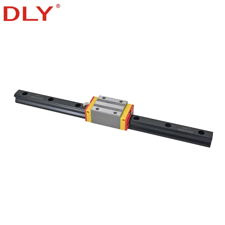
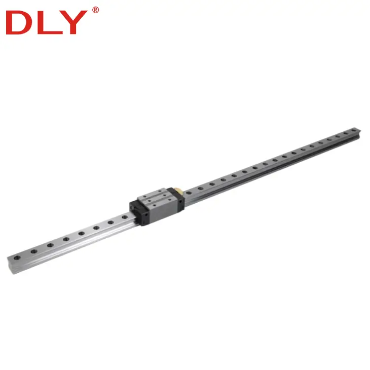
DLY supplies HD heavy-load ball guideways, ED low-profile guideways, MD miniature guideways and RD roller guideways. The correct series should be selected according to load, rigidity, installation space and motion accuracy-not according to a different alignment procedure for each product name.
View available DLY linear guideway series .
Conclusion
To align a linear guideway accurately, first establish a reliable mounting datum, install the master rail, align the secondary rail relative to it and verify both lateral and vertical variation. Final inspection must be performed after all bolts reach their specified torque.
The acceptable alignment error depends on rail length, accuracy grade, preload, block arrangement and machine requirements. When no tolerance is shown on the assembly drawing, confirm it with the guideway or machine manufacturer instead of applying a single value to every installation.
Need Help Selecting a Linear Guideway?
Send DLY your guideway model, rail length, block quantity, accuracy requirement and machine drawing. Our team can help confirm the appropriate rail-and-block configuration.
Email: export@dlybearing.com
Contact DLY


