


SFY ball screw nuts are distinguished by their central flange and end-cap ball circulation structure. They are mainly used with high-lead ball screws in fast linear feed systems where stable ball return, compact mounting and controlled running performance are required.
The main difference is not that SFY nuts are automatically more accurate than every other nut type. Their value comes from matching the circulation structure, flange position and available lead range to the operating speed and machine layout.
What Is an SFY Ball Screw Nut?
An SFY nut is a single flanged ball screw nut with a Y-type central flange and an end-cap circulation system. The balls roll between the screw and nut raceways, then return through passages formed by the end caps.
In the SFY designation:
- S indicates a single-nut structure;
- F indicates a flanged mounting structure;
- Y identifies the Y-type nut design used in this series.
The flange is positioned around the middle of the nut body rather than only at one end. This mounting arrangement can be useful when the nut must connect to a machine table, moving bracket or compact actuator structure.
Why Does SFY Use End-Cap Circulation?
In an end-cap circulation nut, the balls are guided from one end of the loaded raceway to the other through return paths formed in the end caps. This structure is commonly used for large-lead ball screws because it provides a continuous circulation path around the nut body.
The main engineering benefits can include:
- Stable ball circulation at higher linear travel speeds;
- Compatibility with large screw leads;
- A relatively compact nut body for the available circulation structure;
- Reduced circulation impact when the return path is correctly manufactured and assembled;
- Suitability for rapid-feed and repeated positioning axes.
These benefits still depend on the selected model, ball screw accuracy, preload, lubrication, installation alignment and operating speed. An end-cap structure cannot compensate for an incorrectly installed or poorly supported screw assembly.
Why Is SFY Suitable for High-Lead Ball Screws?
High-lead ball screws generate more linear travel for each screw revolution. For example, an SFY2020 has a nominal screw diameter of 20 mm and a lead of 20 mm, while an SFY2525 has a 25 mm diameter and a 25 mm lead.
A larger lead can produce high linear speed without requiring the same rotational speed as a smaller-lead screw. However, it also increases the helix angle and places greater demands on ball circulation, acceleration control and nut design.
DLY's current SFY range includes models such as:
| Model | Nominal Screw Diameter | Lead | General Design Direction |
|---|---|---|---|
| SFY1616 | 16 mm | 16 mm | Compact high-lead feed axis |
| SFY2020 | 20 mm | 20 mm | Fast automation and positioning axis |
| SFY2525 | 25 mm | 25 mm | Larger rapid-feed mechanism |
| SFY3232 | 32 mm | 32 mm | Higher-capacity fast linear axis |
| SFY4040 | 40 mm | 40 mm | Large high-lead transmission system |
| SFY2040 | 20 mm | 40 mm | Very high linear travel per revolution |
These model dimensions show why SFY is associated with high-lead motion, but they do not determine the correct model by themselves. Load, speed, stroke, support arrangement and installation space must also be checked.
SFY vs SFU and SFNU Ball Nuts
SFY, SFU and SFNU are all ball nut structures, but they are not interchangeable simply because the nominal screw diameter and lead appear similar.
| Nut Series | Typical Structure | Main Selection Direction | Important Check |
|---|---|---|---|
| SFY | Central flange with end-cap circulation | High-lead and high-speed feed systems | Flange position, lead, circulation speed and mounting space |
| SFU | Common end-flange ball nut structure | General CNC, automation and compact linear motion | Flange dimensions, nut length and matching screw model |
| SFNU | Flanged nut structure with its own dimensional series | Applications requiring the corresponding SFNU mounting dimensions | Outer diameter, flange pattern, length and interchangeability |

A standard round-flange SFU nut has a different flange position and body structure from an SFY nut.
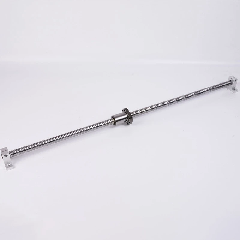
An SFNU assembly must be compared by nut dimensions and mounting structure, not only by screw diameter.
The two images above are useful as structural comparisons, but neither product should be presented as an SFY nut. For replacement projects, the original nut drawing or complete dimensional measurements are more reliable than selecting by series name alone.
Does SFY Automatically Provide Higher Accuracy?
No. SFY describes the nut structure and circulation design; it does not by itself define the complete ball screw accuracy grade.
Positioning performance also depends on:
- The lead accuracy of the matching ball screw shaft;
- Axial clearance or preload;
- Nut and support-bearing rigidity;
- Screw straightness and installation alignment;
- Thermal expansion during repeated high-speed movement;
- Motor, coupling and feedback-system performance.
A standard SFY assembly selected for fast transport and a precision SFY assembly selected for controlled positioning may use the same basic nut structure but require different screw accuracy, preload and inspection requirements.
Does SFY Eliminate Backlash?
An SFY nut can be supplied with controlled axial clearance or preload, but it should not be described as having zero backlash under every condition.
Backlash and lost motion may come from several parts of the axis:
- Clearance inside the ball screw nut;
- Support-bearing axial movement;
- Loose coupling or shaft connection;
- Movement between the nut flange and mounting bracket;
- Elastic deformation under reversing load;
- Wear or incorrect installation.
Increasing nut preload can improve rigidity and reduce axial clearance, but it also increases running torque and heat. Preload must be selected according to the required load, speed, accuracy and drive capacity.
What Applications Are Suitable for SFY Nuts?
SFY nuts are most relevant where the application benefits from a large screw lead and rapid linear movement. Possible uses include:
- Rapid-feed axes in CNC and machining equipment;
- Loading and unloading mechanisms;
- Automatic transfer and positioning units;
- Semiconductor and electronic manufacturing equipment;
- Medical-equipment positioning systems;
- Packaging and assembly machinery;
- Long-stroke automation axes requiring fast cycle times.
The term "high speed" should be evaluated using the required linear velocity and screw lead. For the same linear speed, a 20 mm lead requires fewer screw revolutions than a 5 mm lead, but acceleration, nut circulation and support-bearing limits still need to be checked.
What Must Be Checked Before Replacing Another Nut with SFY?
An SFY nut cannot normally replace an SFU or SFNU nut without checking the mechanical interface. The following dimensions may differ:
- Nut outside diameter;
- Overall nut length;
- Flange location and thickness;
- Flange outside dimensions;
- Mounting-hole quantity, diameter and pitch-circle position;
- Screw lead and ball-track geometry;
- Oil hole or lubrication connection;
- Required installation clearance around the end caps.
For maintenance replacement, provide the complete original model, nut drawing and clear photos from the front, side and flange face. Providing only the screw diameter and lead is not enough to confirm interchangeability.
Installation and Lubrication Considerations
The end-cap circulation structure should be protected from impact during transportation and installation. Damage or displacement around the return components can affect ball circulation.
During assembly:
- Keep the ball nut on the matching screw or a suitable transfer sleeve.
- Do not allow the nut to run beyond the end of the screw thread.
- Align the nut flange with the moving bracket before final tightening.
- Confirm that the screw support units and guide rails are correctly aligned.
- Rotate the assembly slowly through the full stroke before powered operation.
- Apply the specified grease or oil through the correct lubrication point.
- Check running torque and temperature after initial operation.
If the nut runs smoothly before being fixed to the machine but becomes tight after the flange bolts are tightened, the likely cause is installation misalignment rather than the SFY circulation structure itself.
What Information Is Needed to Select an SFY Nut?
For model selection or quotation, provide:
- Required screw diameter and lead;
- Total screw length and effective stroke;
- Maximum linear speed;
- Normal and peak axial load;
- Required positioning accuracy or screw accuracy grade;
- Required axial clearance or preload;
- Nut flange and installation-space limitations;
- Support-unit arrangement and end-machining drawing;
- Lubrication method and operating environment;
- Existing model or sample dimensions for replacement projects.
Review the available structure and current model data on the DLY SFY ball screw nut page.
For applications where high linear speed is the main requirement, the screw lead should also be evaluated together with rotational speed. See high-lead ball screw options for the broader transmission structure.
Final Answer
The distinguishing feature of an SFY nut is its central flange and end-cap circulation structure, which makes the series suitable for high-lead and fast-feed ball screw systems. It is not defined by a metaphorical "taste," nor is it automatically more accurate than every SFU or SFNU nut.
The correct nut should be selected from the required diameter, lead, speed, load, preload, accuracy and mounting dimensions. For replacement projects, verify the complete nut interface rather than relying only on the series name.
To confirm an SFY model, send DLY the screw diameter, lead, speed, stroke, load, accuracy requirement and nut installation drawing. DLY can check the matching nut, screw shaft, end machining and support-unit arrangement.


