EK EF Ball Screw End Supports for Compact Ball Screw Assemblies
DLY EK and EF ball screw end supports are used to support both ends of a ball screw shaft in compact linear motion assemblies. The EK unit is installed on the fixed side of the ball screw, while the EF unit is installed on the support or floated side. Together, they help maintain shaft alignment, support smooth rotation, and improve the stability of the complete ball screw drive system.
Compared with larger BK/BF support units, EK/EF supports are often selected for smaller ball screw sizes, compact machine structures, light automation axes, linear modules, measuring equipment, and CNC auxiliary mechanisms where installation space is limited but stable end support is still required.
DLY supplies EK and EF ball screw support units in common compact sizes, including EK5, EK6, EK8, EK10, EK12, EK15, EK20 and matching EF support units. The suitable model should be confirmed according to the ball screw shaft end machining, bearing bore, mounting hole layout, installation space, and fixed or floated end arrangement.

EK EF ball screw end support set with fixed support, floated support, lock nut, and retaining ring.

EF floated side support unit for the support end of a ball screw shaft.

EK and EF support units used together for fixed-side and floated-side ball screw installation.

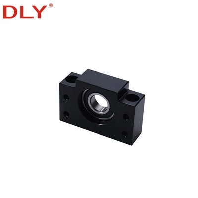
EK fixed side support unit for compact ball screw assemblies.
EK Fixed Side and EF Floated Side
In a typical ball screw assembly, one end of the screw shaft needs to be positioned firmly to control axial movement. This side is usually called the fixed side. The EK ball screw end support is used for this position. It contains bearings inside the support block and is normally used together with the machined screw shaft end, lock nut, and retaining components.
The opposite end of the ball screw is usually used as the support or floated side. The EF ball screw end support helps support the shaft while allowing the system to compensate for small axial changes caused by assembly tolerance, thermal expansion, or operating conditions. Using EK and EF together helps prevent unnecessary binding and keeps the ball screw running more smoothly.
| Support Type | Installation Position | Main Function | Typical Matching Part |
|---|---|---|---|
| EK Support | Fixed side of the ball screw | Controls the axial position of the screw shaft and supports accurate rotation. | Machined shaft end, lock nut, retaining ring, and motor-side coupling structure. |
| EF Support | Floated or support side of the ball screw | Supports the shaft end while allowing small axial compensation in the assembly. | Support-side machined shaft end and bearing support structure. |
Product Structure and Features
EK and EF ball screw support units are compact block-type supports with mounting holes on both sides. The support body provides a stable installation base, while the internal bearing arrangement supports the machined screw shaft end. The black surface finish and compact block structure make the support units suitable for installation inside linear modules, small CNC axes, automation slides, and precision positioning mechanisms.
The EK fixed support is normally selected for the drive side or positioning side of the ball screw. The EF floated support is selected for the opposite side. When the ball screw is ordered with end machining, the shaft end dimensions should match the selected EK/EF support model, including bearing inner diameter, thread section, lock nut position, and shaft shoulder design.
| Product Name | EK EF Ball Screw End Supports |
|---|---|
| Support Types | EK fixed side support and EF floated side support |
| Common Models | EK5, EK6, EK8, EK10, EK12, EK15, EK20; EF6, EF8, EF10, EF12, EF15, EF20 |
| Matched Components | Ball screw shaft end, lock nut, retaining ring, coupling, motor bracket, and machine mounting base |
| Main Use | Supporting compact ball screw assemblies in CNC, automation, linear modules, measuring equipment, and precision machinery |
EK and EF Size Reference
The following original size drawings are retained for quick visual comparison. They show several common EK and EF support combinations, including EF8/EK8, EF10/EK10, EF12/EK12, and EF15/EK15. For production use, please confirm the final dimensions together with the selected ball screw shaft end machining drawing.

EF8 and EK8 ball screw end support dimension drawing.

EF10 and EK10 ball screw end support dimension drawing.

EF12 and EK12 ball screw end support dimension drawing.

EF15 and EK15 ball screw end support dimension drawing.
| Model Group | Support Role | Common Use | Selection Reminder |
|---|---|---|---|
| EK5 / EK6 / EK8 | Fixed side support | Small ball screw assemblies, compact modules, light-duty automation axes | Confirm shaft end machining, bearing bore, and lock nut space. |
| EK10 / EK12 / EK15 / EK20 | Fixed side support | CNC axes, packaging equipment, precision positioning systems, linear modules | Confirm mounting height, hole spacing, and matching coupling layout. |
| EF6 / EF8 / EF10 / EF12 / EF15 / EF20 | Floated side support | Support end of the ball screw opposite the fixed side | Select the EF support together with the matching EK fixed-side unit and screw shaft end design. |
EK Fixed Side Parameter Drawing
The EK fixed-side drawing below shows the installation dimensions for EK support units. It includes the support body width, mounting hole position, center height, shaft bore, and related shaft end reference dimensions. This image should be kept on the page because it helps users quickly check whether the support block fits their ball screw end design.

EK fixed side ball screw support parameter drawing and size table.
EF Floated Side Parameter Drawing
The EF floated-side drawing below shows the support-side dimensions for EF units. EF supports are usually selected together with the corresponding EK fixed support, so the screw shaft end machining should be checked as a complete set rather than as a single block only.

EF floated side ball screw support parameter drawing and size table.
How to Select EK and EF Ball Screw Supports
Selection should start from the ball screw shaft diameter and shaft end machining. The bearing bore, thread section, lock nut position, shoulder diameter, and support block mounting height must match the EK/EF support unit. If the screw shaft is purchased together with the support units, it is better to confirm the end machining drawing before production.
For most assemblies, the EK fixed support is placed on the motor side because this side needs accurate axial positioning and coupling connection. The EF floated support is placed at the opposite end to support the shaft and reduce the risk of binding caused by thermal expansion or small assembly deviation.
| Selection Item | What to Confirm |
|---|---|
| Ball screw model | Screw diameter, lead, nut type, and total shaft length. |
| End machining | Bearing seat diameter, thread size, shoulder position, keyway or coupling section if required. |
| Support combination | EK fixed support for the positioning side and EF floated support for the support side. |
| Mounting space | Support block height, body width, mounting hole distance, and machine base layout. |
| Drive connection | Coupling type, motor bracket, lock nut clearance, and assembly direction. |
| Operating condition | Speed, stroke, duty cycle, load condition, working temperature, and lubrication environment. |
Typical Applications
EK and EF ball screw end supports are widely used in compact linear motion systems that require accurate screw shaft support. Common applications include CNC equipment, engraving machines, measuring instruments, semiconductor auxiliary equipment, packaging machinery, small automation axes, linear modules, laboratory equipment, and precision positioning platforms.
For applications that require a complete ball screw assembly, DLY can supply ball screws, ball nuts, end machining, EK/EF supports, BK/BF supports, FK/FF supports, couplings, and related linear motion components. Providing the assembly drawing or machine layout helps us confirm the correct support model more accurately.
Installation Notes
During installation, the support blocks should be mounted on a flat and rigid surface. The fixed-side EK support, ball screw shaft, coupling, and motor shaft should be aligned carefully to reduce additional radial load. The floated-side EF support should be installed without forcing the shaft into a misaligned position.
After assembly, rotate the ball screw by hand before connecting the motor drive. The screw should rotate smoothly without abnormal resistance. If tightness, noise, or uneven rotation occurs, check the support block alignment, shaft end machining, lock nut installation, coupling concentricity, and mounting surface flatness.
FAQ About EK EF Ball Screw End Supports
Q: What is the difference between EK and EF ball screw supports?
A: EK is the fixed-side support used to locate one end of the ball screw shaft. EF is the floated-side support used at the opposite end to support the shaft while allowing small axial compensation in the assembly.
Q: Should EK and EF be used together?
A: In many compact ball screw assemblies, EK and EF are used as a pair. EK is normally installed on the motor or fixed side, and EF is installed on the support side. This arrangement helps the screw shaft rotate smoothly and reduces the risk of axial binding.
Q: How do I choose the correct EK or EF model?
A: The model should be selected according to the ball screw shaft diameter, shaft end machining, bearing bore, support block height, mounting hole distance, and machine installation space. If the end machining has not been designed yet, DLY can help confirm the support model before production.
Q: Can DLY supply ball screws with EK/EF supports together?
A: Yes. DLY can supply ball screws, ball nuts, end machining, EK/EF supports, BK/BF supports, FK/FF supports, and couplings as matched linear motion components. Please provide the ball screw model, length, end machining requirements, and support unit model for confirmation.
Q: What information should I provide for quotation?
A: Please provide the EK/EF model, quantity, matching ball screw size, shaft end drawing, installation layout, and whether lock nuts, retaining rings, couplings, or complete ball screw assemblies are needed.
Need help confirming the right model?
Contact DLY for model selection, drawing confirmation, quotation, and delivery details. Email: export@dlybearing.com
Hot Tags: ek ef ball screw end supports, China ek ef ball screw end supports manufacturers, suppliers, factory