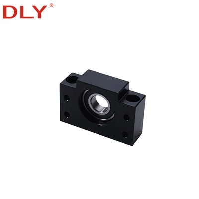
BK Fixed Side vs. BF Floating Side
| Item | BK Fixed-Side Support | BF Floating-Side Support |
|---|---|---|
| Installation position | Motor, coupling or drive side | Opposite end of the screw shaft |
| Main function | Axial location and fixed-end support | Support for the non-drive shaft end |
| Selection focus | Fixed-end shaft diameter, shoulder, thread and support dimensions | Floating-end journal diameter and support dimensions |
| Mounting form | Square housing with base mounting holes | Matching square housing with base mounting holes |
| Typical ordering method | Ordered separately or as the BK side of a matched set | Ordered separately or as the matching BF side |


Matched BK/BF Models and Shaft-End Diameters
The BK and BF model numbers indicate a matched support group, but the fixed-side and floating-side shaft-end diameters are not always identical. BK10/BF10 and BK12/BF12 are the most important examples to check before machining.
| Matched Pair | BK Fixed-End d1 (mm) | BF Floating-End d1 (mm) | Housing Width B (mm) | Housing Height H (mm) | Center Height h (mm) | Mounting Pitch P (mm) |
|---|---|---|---|---|---|---|
| BK10 / BF10 | 10 | 8 | 60 | 39 | 22 | 46 |
| BK12 / BF12 | 12 | 10 | 60 | 43 | 25 | 46 |
| BK15 / BF15 | 15 | 15 | 70 | 48 | 28 | 54 |
| BK17 / BF17 | 17 | 17 | 86 | 64 | 39 | 68 |
| BK20 / BF20 | 20 | 20 | 88 | 60 | 34 | 70 |
| BK25 / BF25 | 25 | 25 | 106 | 80 | 48 | 85 |
| BK30 / BF30 | 30 | 30 | 128 | 89 | 51 | 102 |
| BK35 / BF35 | 35 | 35 | 140 | 96 | 52 | 114 |
| BK40 / BF40 | 40 | 40 | 160 | 110 | 60 | 130 |
BK Fixed-Side Support Dimensions
All dimensions are in millimetres. The values for b and h have a tolerance of ±0.02 mm. Mounting holes are specified as 4-X drill-through holes with ØY counter bores and counter-bore depth Z.

| BK Model | d1 | L | L1 | L2 | L3 | C1 | C2 | B | H | b ±0.02 | h ±0.02 | B1 | H1 | E | P | d2 | X | Y | Z |
|---|---|---|---|---|---|---|---|---|---|---|---|---|---|---|---|---|---|---|---|
| BK10 | 10 | 25 | 5 | 29 | 5 | 13 | 6 | 60 | 39 | 30 | 22 | 34 | 32.5 | 15 | 46 | 5.5 | 6.6 | 10.8 | 5 |
| BK12 | 12 | 25 | 5 | 29 | 5 | 13 | 6 | 60 | 43 | 30 | 25 | 34 | 32.5 | 18 | 46 | 5.5 | 6.6 | 10.8 | 1.5 |
| BK15 | 15 | 27 | 6 | 32 | 6 | 15 | 6 | 70 | 48 | 35 | 28 | 40 | 38 | 18 | 54 | 5.5 | 6.6 | 11 | 6.5 |
| BK17 | 17 | 35 | 9 | 44 | 7 | 19 | 8 | 86 | 64 | 43 | 39 | 50 | 55 | 28 | 68 | 6.6 | 9 | 14 | 8.5 |
| BK20 | 20 | 35 | 8 | 43 | 8 | 19 | 8 | 88 | 60 | 44 | 34 | 52 | 50 | 22 | 70 | 6.6 | 9 | 14 | 8.5 |
| BK25 | 25 | 42 | 12 | 54 | 9 | 22 | 10 | 106 | 80 | 53 | 48 | 64 | 70 | 33 | 85 | 9 | 11 | 17.5 | 11 |
| BK30 | 30 | 45 | 14 | 61 | 9 | 23 | 11 | 128 | 89 | 64 | 51 | 76 | 78 | 33 | 102 | 11 | 14 | 20 | 13 |
| BK35 | 35 | 50 | 14 | 67 | 12 | 26 | 12 | 140 | 96 | 70 | 52 | 88 | 79 | 35 | 114 | 11 | 14 | 20 | 13 |
| BK40 | 40 | 61 | 18 | 76 | 15 | 33 | 14 | 160 | 110 | 80 | 60 | 100 | 90 | 37 | 130 | 14 | 18 | 26 | 17.5 |
BF Floating-Side Support Dimensions
BF dimensions must be checked against the floating-end journal of the ball screw. Do not infer the journal diameter directly from the BF model number, especially for BF10 and BF12.

| BF Model | d1 | L | B | H | b ±0.02 | h ±0.02 | B1 | H1 | E | P | d2 | X | Y | Z |
|---|---|---|---|---|---|---|---|---|---|---|---|---|---|---|
| BF10 | 8 | 20 | 60 | 39 | 30 | 22 | 34 | 32.5 | 15 | 46 | 5.5 | 6.6 | 10.8 | 5 |
| BF12 | 10 | 20 | 60 | 43 | 30 | 25 | 34 | 32.5 | 18 | 46 | 5.5 | 6.6 | 10.8 | 1.5 |
| BF15 | 15 | 20 | 70 | 48 | 35 | 28 | 40 | 38 | 18 | 54 | 5.5 | 6.6 | 11 | 6.5 |
| BF17 | 17 | 23 | 86 | 64 | 43 | 39 | 50 | 55 | 28 | 68 | 6.6 | 9 | 14 | 8.5 |
| BF20 | 20 | 26 | 88 | 60 | 44 | 34 | 52 | 50 | 22 | 70 | 6.6 | 9 | 14 | 8.5 |
| BF25 | 25 | 30 | 106 | 80 | 53 | 48 | 64 | 70 | 33 | 85 | 9 | 11 | 17.5 | 11 |
| BF30 | 30 | 32 | 128 | 89 | 64 | 51 | 76 | 78 | 33 | 102 | 11 | 14 | 20 | 13 |
| BF35 | 35 | 32 | 140 | 96 | 70 | 52 | 88 | 79 | 35 | 114 | 11 | 14 | 20 | 13 |
| BF40 | 40 | 37 | 160 | 110 | 80 | 60 | 100 | 90 | 37 | 130 | 14 | 18 | 26 | 17.5 |
Dimension symbols follow the supplied BK and BF drawings. Confirm the final support drawing together with the machined ball screw end drawing before production.
How to Select a BK/BF Support Set
For a New Ball Screw Assembly
- Confirm the ball screw diameter, lead, total length and nut type.
- Select the BK/BF housing size according to the machine base and shaft-end design.
- Design the fixed and floating shaft ends from the correct BK and BF d1 values.
- Check B, H, h, P, b and the mounting-hole specifications against the machine drawing.
- Confirm whether the ball screw, end machining, supports, coupling and related accessories are required together.
For Replacement
- Send the existing BK/BF model or clear photos of both supports.
- Measure the shaft center height, housing width, mounting pitch and hole sizes.
- Provide the fixed-end and floating-end shaft dimensions.
- Confirm the coupling and motor-side layout before ordering.
- Use the final approved drawing rather than relying on model markings alone.
For a more compact support structure, see the EK/EF ball screw support units. For flange mounting, see the FK/FF ball screw support units.
Ordering Information
For faster confirmation, send the BK/BF model, quantity, ball screw diameter and lead, total screw length, fixed-end and floating-end machining drawing, mounting layout, and whether a complete ball screw assembly is required. DLY can check the support units together with the ball screw, ball nut, end machining and coupling.
Contact DLY for BK/BF Model Confirmation
Send your shaft-end drawing, existing support model or machine installation dimensions.
Email: export@dlybearing.com
Contact DLYHot Tags: bk bf ball screw end support, China bk bf ball screw end support manufacturers, suppliers, factory