


A linear guide slider supports a moving machine component and keeps it travelling along a controlled straight path. It carries radial and moment loads through rolling balls or rollers while limiting unwanted movement in other directions.
The slider does not normally produce the driving force. In a complete linear axis, a ball screw, belt, rack, pneumatic cylinder or other actuator moves the table, while the linear guide rail and sliders support, guide and stabilize it.
How a Linear Guide Slider Works
A profile linear guide system consists mainly of a hardened rail and one or more matching slider blocks. Inside a ball-type slider, steel balls roll along the loaded raceways between the block and rail. They then pass through a return path inside the slider and circulate continuously as the block moves.
The rolling elements provide low-resistance movement while transmitting the applied load from the moving table into the guide rail and machine base. End caps guide ball circulation, seals help limit contaminant entry, and the lubrication system supplies grease or oil to the rolling contact.
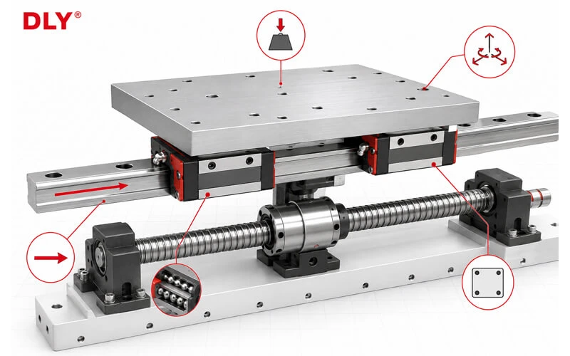
Five Main Functions of a Linear Guide Slider
1. Support the Moving Load
The slider transfers the weight of the moving table, tooling and workpiece into the rail and machine structure. Depending on the guideway design and mounting direction, the block may carry downward, upward or lateral loads.
Load capacity should not be evaluated only from the total machine weight. Acceleration, cutting force, pressing force, vibration and offset loads can make the actual block load much higher than the static weight calculation suggests.
2. Maintain Straight and Stable Travel
The matched raceways of the rail and block constrain the carriage so that it follows the rail direction. This helps reduce lateral movement, vertical displacement and angular variation as the table travels.
The final straightness and running accuracy of the machine still depend on the rail accuracy, mounting-surface quality, rail alignment, block arrangement and rigidity of the surrounding structure.
3. Reduce Friction During Motion
Recirculating balls or rollers replace most sliding contact with rolling contact. This reduces the drive force required to move the table and supports smooth starting, stopping and direction reversal.
Low friction does not mean that the guideway can operate without lubrication. Lubrication is required to reduce raceway wear, limit heat and protect the contact surfaces. Seals, preload and lubricant viscosity also contribute to the measured running resistance.
4. Resist Roll, Pitch and Yaw Moments
A load that acts away from the center of the slider arrangement creates a moment. Depending on its direction, the moment tends to rotate the table around the travel axis, transverse axis or vertical axis.
A linear guide slider can resist moment loads through its raceway contact geometry, but the complete capacity depends on block size, block type, rail spacing, longitudinal block spacing and the number of sliders.
For calculation examples, see Linear Guide Moment Load Calculation: Roll, Pitch and Yaw.
5. Provide a Mounting Interface
The upper mounting surface and threaded holes of the slider connect it to the moving table, fixture or machine component. Square blocks, flange blocks, low-profile blocks and miniature blocks provide different mounting dimensions and installation options.
The mounting plate should be sufficiently rigid and accurately machined. A distorted or uneven plate can force the sliders out of alignment, creating high running resistance and uneven internal loading.
Linear Guide Slider vs Drive Component
One of the most important distinctions in linear-axis design is the difference between guiding the load and driving the load.
| Component | Main Function | What It Does Not Normally Do |
|---|---|---|
| Linear guide rail and slider | Support load, control direction and resist unwanted displacement | Generate the force required to move the axis |
| Ball screw | Convert motor rotation into controlled linear movement | Independently resist all side and moment loads |
| Timing belt | Provide fast linear transmission over suitable travel lengths | Provide high-rigidity guidance for the moving table |
| Pneumatic or hydraulic cylinder | Generate linear pushing or pulling force | Replace precision external guidance in demanding offset-load applications |
Allowing the ball screw or cylinder rod to carry significant side loads can increase wear, cause binding and reduce positioning stability. The guideway should carry and constrain the moving structure, while the drive component supplies motion in the intended direction.
Why Slider Quantity and Layout Matter
A single slider may be sufficient for a compact, well-centered and relatively light application, but it has limited ability to resist large moment loads. Machine tables commonly use two blocks on one rail or four blocks distributed across two parallel rails.
| Arrangement | General Characteristic | Main Point to Check |
|---|---|---|
| One rail, one block | Compact structure for limited load and moment requirements | Block moment capacity and platform stability |
| One rail, two blocks | Improved resistance to pitch and yaw moments | Distance between blocks and mounting-plate rigidity |
| Two rails, four blocks | Higher table stability and better multi-directional load support | Parallelism, rail spacing and equal load distribution |
Adding more sliders does not automatically divide the load equally. Mounting error, uneven rail height, structural deformation and off-center forces may cause one block to carry a much larger share of the load.
What to Confirm When Selecting a Linear Guide Slider
When selecting or replacing a slider, confirm:
- Guideway series and rail size
- Square, flange, low-profile, miniature or roller block structure
- Load magnitude and direction
- Roll, pitch and yaw moments
- Number of rails and blocks
- Rail spacing and block spacing
- Required preload and rigidity
- Accuracy grade
- Speed, acceleration and duty cycle
- Lubrication method and maintenance access
- Dust, chips, moisture and other environmental conditions
- Mounting-hole pattern and installation space
DLY linear guideways are available with C, H, P, SP and UP accuracy options, subject to the selected series and project requirements. A higher grade should be chosen only when the machine structure, mounting surfaces and installation method can make effective use of it.
For a broader explanation of slider structures and types, see Linear Guide Slider: Types, Structure and Selection.
DLY supplies matched linear guide rails and slider blocks. Send the rail model, block model, load, rail length, block quantity, accuracy grade, drawing or sample photo for confirmation.
Email: export@dlybearing.com


